EDM machining - Scientific Industrial Corporation DELTA-TEST / Electrical Discharge Machine Tools (EDM) and Technologies ARTA
Main menu:
- Home
- Company
- Products and Service
- Consumables
- EDM machining
- Request info
- Contact Us
EDM machining
EDM Machining


SIC Delta-
2 -
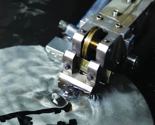
5- axis wire EDM machining maximum dimensions of workpieces W x L x H = 420 x 300 x 150 mm (workpiece weight up to 100 kg)
wire-
tool diameter from 0.02 mm to 0.30 mm batch cutting
EDM machining with CNC controlled rotary axis
machinig of non-
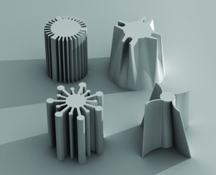
standard materials (graphite, magnets, PCD- tools and others) development of CNC programs
development of specific technologies (wire-
cut and sinker EDM machining)
Source data -
In order to accelerate the start-
Here are some tips on preparing an original path in the environment of AutoCAD:
1. All of the elements of the contour should be drawn at a scale of 1:1 (1 unit = 1 mm, the minimal value (mininal step) is 0.001 units = 1 µm).
2. Each element of the path must be a Line, Circle or Arc. In case of using splines and ellipses -
3. Endpoints are common to two neighboring circuit elements must be connected (be the same). This fact can be verified by combining all of the circuit elements in a single polyline, which in the future will be directly used to obtain the control program:
3.1. At the command prompt enter the command "pedit" (can also be selected using the top menu: Modify Polyline)
3.2. In response, we get: "Select polyline or [Multiple]"
3.3. Select with the mouse any element of the circuit and in response to the message 'Object selected is not a polyline Do you want to turn it into one? <Y>' press 'Enter'
3.4. Next, the join command (J) combine the remaining circuit elements into a single polyline.
In case of successful execution of the above operations, the circuit will be a single polyline -
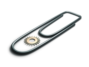
4. For complex circuits with a large number of individual elements such as toothed wheel, etc., it should be borne in mind that for suciently 'small' items sometimes it impossible to carry out normal correction (offset) on the value of the cut groove. An example of such situation is given in the following figure, after the implementation of the offset is 'missing' the arc of the circle.